English
 English
 Español
 Português
 русский
 français
 日本語
日本語 Deutsch
 Tiếng Việt
 Italiano
 Nederlands
 ไทย
ไทย Polski
 한국어
한국어 Svenska
 magyar
 Malay
Malay বাংলা
বাংলা Dansk
Dansk Suomi
Suomi हिन्दी
 Pilipino
 Türk
Türk Gaeilge
 عربى
عربى Indonesia
 norsk
norsk اردو
اردو čeština
 Ελληνικά
 Українська
 Javanese
 فارسی
فارسی தமிழ்
தமிழ் తెలుగు
 नेपाली
 Burmese
 български
 ລາວ
ລາວ Latine
 Қазақ
Қазақ Euskal
 Azərbaycan
 slovenský
 Македонски
 Lietuvos
 Eesti Keel
 Română
 Slovenski
 मराठी
मराठी Српски
 Harmony Reducer CSF-32-30-2UH for Closed Slot Shaving Cutter
 Harmonic Assembly Machine CSF-20-100-2UH-SP
 Harmony Inertia Drum Gear Harmonic Unit CSF-20-120-2UH
 Harmonyx Flex Pulley Harmonic Module CSF-25-30-2UH
 Harmonic Reducer CSF-25-50-2UH
 Hammerner Kohler Gear Displacement Harmonic Reducer CSF-25-80-2UH
- All new products
Harmonic Drive Spring Steel Harmonic FHA-40C-100-E250-C
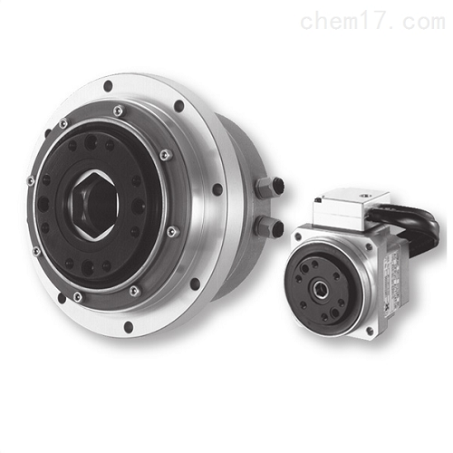
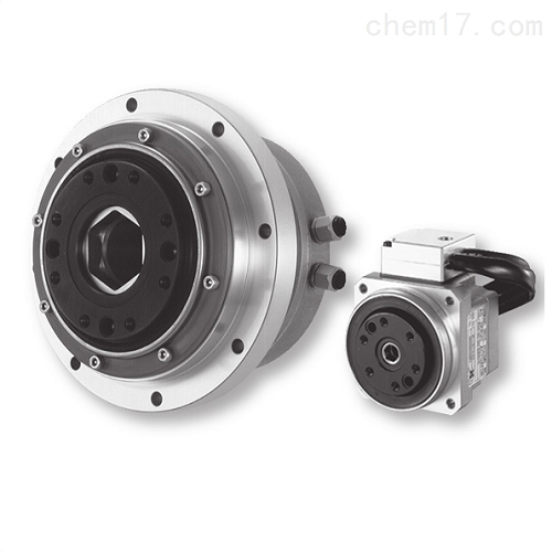
The Japanese Harmonic Drive DD motor drive FHA-40C-100-E250-C primarily consists of four basic components: a wave generator, a flexible gear, a flexible bearing, and a rigid gear. This harmonic drive reducer is a type of gear transmission that relies on the wave generator to assemble the flexible bearing, allowing the flexible gear to undergo controlled elastic deformation and mesh with the rigid gear to transmit motion and power. The number of teeth on the flexible gear is fewer than the number of teeth on the rigid gear. When the wave generator rotates, the external teeth of the flexible gear mesh precisely into the internal teeth of the rigid gear along the longitudinal axis.
This design is widely used in precise and efficient industrial applications, aiming to provide reliable power transmission and precise motion control.
Product Description
SHA series
Abstract
Specialties
HarmonicDrive ® Integrated AC servo actuator with specially designed flat AC servo motor
Hollow and flat structure
Absolute value encoder
SHA-SG: Compact shape with extra length
SHA-CG: For turntable use, improve the accuracy of output shaft surface vibration

1. Model name: AC servo actuator SHA series
2. Model:
SG type=20, 25, 32, 40, 45, 58, 65
HP type=25,32
CG type=20,25,32,40
3. Version symbols
4. HarmonicDrive ® Reduction ratio:
SG type=51,81101121161
HP type=11
CG type=50,80100120160
5. Type of reducer:
SG type=SHG series
HP type=HPF series
CG type=CSG series
6. Motor version symbol:
A=Models 58, 65
B=Models 25, 32, 40
C=Model 20
D=Model 45
7. Motor size:
● 08=Model 20
09=Model 25
12=Model 32
15=Model 40
16=Model 45
21=Models 58, 65
8. Brake:
● A=No brake
● B=With brake
9. Motor power supply voltage:
100=AC100V
200=AC200V
10. Encoder format:
10=symbol A format, transmission speed: 2.5Mbps, 1:1 connection
11. Encoder type and resolution:
S17b=17bit absolute encoder 131072 pulses/rotation
12. Encoder phase angle:
The phase difference A between the U-phase induced voltage of the motor and the absolute origin is 0 degrees
13 connector specifications:
● C=With standard connectors
● N=No connector
D=With special connectors
14. Optional symbols:
L=Near Origin&End Limit Sensor
Y=Cable side exit
● V=With bracket (CG type only)
● S=Output shaft 1 rotation absolute value specification (CG type only)
● No entry=standard product
SP=non-standard product


