English
 English
 Español
 Português
 русский
 français
 日本語
日本語 Deutsch
 Tiếng Việt
 Italiano
 Nederlands
 ไทย
ไทย Polski
 한국어
한국어 Svenska
 magyar
 Malay
Malay বাংলা
বাংলা Dansk
Dansk Suomi
Suomi हिन्दी
 Pilipino
 Türk
Türk Gaeilge
 عربى
عربى Indonesia
 norsk
norsk اردو
اردو čeština
 Ελληνικά
 Українська
 Javanese
 فارسی
فارسی தமிழ்
தமிழ் తెలుగు
 नेपाली
 Burmese
 български
 ລາວ
ລາວ Latine
 Қазақ
Қазақ Euskal
 Azərbaycan
 slovenský
 Македонски
 Lietuvos
 Eesti Keel
 Română
 Slovenski
 मराठी
मराठी Српски


Harmonic Drive Intensity Flange Harmonic Gearbox CSF-14-80-2UH
The Harmonic Drive Rotating Clamp Harmonic Gear Reducer CSF-14-50-2UH primarily consists of four basic components: the wave generator, flexible gear, flexible bearing, and rigid gear. It is a harmonic transmission reducer that utilizes a wave generator assembled with flexible bearings to induce controlled elastic deformation in the flexible gear. This allows it to mesh with the rigid gear to transmit motion and power in the gear transmission. The number of teeth on the flexible gear's outer circumference is fewer than the number of teeth on the rigid gear's inner circumference. When the wave generator rotates, the teeth on the flexible gear's outer circumference precisely engage with the teeth on the rigid gear's inner circumference.
Product Description
gearbox
Abstract
Harmonic Drive Intensity Flange Harmonic Gearbox CSF-14-80-2UH-LW uses two types of methods to calculate the strength of its end flanges:
1. One method is specifically designed for flanges subjected to axial loads (including eccentric loads) such as flat gaskets and double cone seals. It employs the Bach method, where the end flanges are longitudinally sectioned to analyze the axial load-induced moments. The resulting bending stresses are kept within allowable limits of the material.
2. The second method is intended for flanges subjected not only to axial loads but also to significant radial (tangential) loads, as seen in Wood-style, Kazar-style, N.E.C.-style flanges, and O-ring or C-ring connected seals. These flanges exhibit axial force, axial bending moments, and radial forces that cause the flanges to expand, resulting in axisymmetric bending.
When handling combined loads, it's necessary to first determine the directions and locations of maximum stresses under various load conditions for the Harmonic Drive Intensity Flange Harmonic Gearbox CSF-14-80-2UH-LW. These stresses are then vectorially added together. As a conservative estimate, the maximum stress values obtained individually under each load condition can be directly summed up.
From a stress analysis perspective, dense reinforcement is optimal, followed by internally and externally reinforced internal extension methods, with the Harmonic Drive Intensity Flange Harmonic Gearbox CSF-14-80-2UH-LW ranking third, internal reinforcement fourth, and external reinforcement fifth.
Regarding manufacturing and processing, while dense reinforcement offers superior performance, it requires integrating the root connection with the shell into a unified structure.
Specialties
It is a combination type equipped with high rigidity bearings (cross roller bearings) that are suitable for servo motors of various companies and have a one click installation feature.
High torque
Long lifespan (increased rated lifespan)
No back gap
CSF series ratio: increases torque capacity by 30%
43% increase in lifespan (10000 hours)
※ Motor matching can be confirmed through selection tools
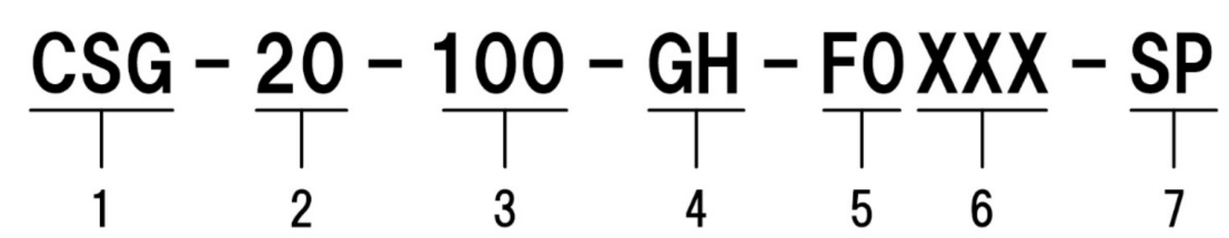
1. Model name: CSG series
2. Models: 14, 20, 32, 45, 65
3. Reduction ratio: 50, 80, 100, 120, 160
4. Type: GH=gearbox type
5. Output shaft shape:
F0=flange output
J2=straight axis (keyless)
J6=Straight axis (with key and center screw hole)
6. The shape of the motor flange and input shaft coupling shall comply with (depending on the installation of the motor)
7. Non standard products:
● Unsigned=standard product
SP=non-standard product


